Silicon IP Cores
White Paper — CANsec: Security for the Third Generation of the CAN Bus
1. Zonal E/E Architecture and Implications for Automotive Cybersecurity
Vehicle electrical/electronic architecture (E/E architecture) is currently undergoing a change from a domain-based to a zonal architecture, breaking through the clear separation into functional domains, such as infotainment, chassis control, or powertrain. In the zonal approach, end devices are not distributed and networked according to their function but by their optimal location within the vehicle, which should significantly reduce the length and weight of the wiring harness. This change leads to significantly greater flexibility because previous concepts required a separate electronic control unit (ECU) for each vehicle function.
Functions can now be combined in fewer ECUs, which will also increase the interoperability and performance of the individual devices in the car. The use of middleware, which serves as a software-based overlay across ECUs, is expected to facilitate cross-functional communication, a concept also known as the software-defined vehicle. Domain-specific data paths are replaced by an infrastructure in which data packets can be forwarded to any other point in the network. The architecture offers many advantages in terms of cost and weight savings but also holds potential for new security vulnerabilities, such as in well-established signal-based communication protocols like the CAN bus.
The CAN bus has been a central element in vehicle E/E architecture for more than 20 years, enabling real-time serial transmission of data between ECUs and sensors. Although it is present in many vehicles, it is vulnerable to security threats.
Developed for the first time in the 1980s, the protocol did not consider cyber threats at that time because networking and connectivity were not yet relevant topics. Later, when the need for secure solutions became apparent, the Automotive Open System Architecture (AUTOSAR) established a solution for signal-based communication in vehicles. However, the Secure-Onboard-Communication (SecOC) module operates on the higher layers of the OSI model and thus entails a lot of software overhead for the individual tasks, which can lead to high CPU utilization.
Security protocols that operate on the lower layers and guarantee real-time protection are, therefore, a useful addition to the vehicle security concept. One solution for securing CAN communication is CANsec. CANsec is part of the third CAN bus generation CAN XL and allows authentication, encryption, and integrity checking of CAN frames.
2. The third generation of the CAN Bus – CAN XL
CAN XL is based on the concepts specified in ISO 11898-1:2015 – Road Vehicles – Controller Area Network (CAN). The characteristics of the CAN XL protocol have been defined by the CAN in Automation Special Interest Group (CiA SIG) since 2018 and are not yet complete. One of the main motivations for the development is to close the bit rate gap between CAN/CAN FD and Ethernet 100 Base-T1 in future vehicle E/E architectures.
Since December 2018, the CiA SIG (Special Interest Group) specifies the features of the CAN XL protocol in the following documents:
- CiA 610: CAN XL – Specification and test plans
- CiA 611: CAN XL – Higher-layer services
- CiA 612: CAN XL – Guidelines and application notes
- CiA 613: CAN XL – Add-on services
The main features, compared to the previous standards Classic CAN and CAN FD, are the high possible bit rate of up to 20 Mbps, as well as the data field length from 1 to 2048 bytes. This allows tunneling of Ethernet frames, which enables both signal-based real-time communication and service-oriented communication over the same network.
CAN XL at a Glance
|
For this purpose, CAN XL offers the new 8-bit fields SDU-Type (SDT) and VCID (Virtual CAN Network ID), which enable the CAN bus to act as a backbone network in the vehicle‘s zonal architecture. SDT indicates the next OSI layer protocol used, which allows the implementation of multiprotocol stacks, which is a necessity if different applications need to run on one cable. The VCID field allows the assignment of virtual CAN IDs. Within a single CAN XL network segment, up to 256 virtual networks can be defined. This allows logical structures to be set up to make work easier.
Another new feature is the division of arbitration and addressing purposes. CAN XL now has an 11-bit Priority ID and a 32-bit Acceptance Field that can contain a node address or a content indicator. In Classical CAN or CAN FD, all of these are contained in the identifier.
The bus access method has not changed: the Carrier Sense Multiple Access/Collision Resolution (CSMA/CR method) is still used, which provides a unique priority concept.
For the physical transmission between the controller and transceiver, the user can use the usual non-return-to-zero (NRZ) coding or the new pulse-width modulation (PWM) coding. With PWM coding, higher bit rates of up to 20 Mbps can be achieved in the data phase.
The CiA also specifies some new features. Fragmenting the data frame allows the frame to be transmitted piecemeal, which optimizes the network latency. Another function is the CANsec security protocol, which prevents unauthorized access to the data link layer.
3. CAN Bus Security
Attacks such as spoofing, sniffing and replay, repudiation, and resource exhaustion on the CAN network of a vehicle are easy as long as no measures are taken against them. Therefore, a solution from AUTOSAR for secure signal-based communication in vehicles has been available for several years. The SecOC module is already implemented in today‘s E/E architectures. However, SecOC acts from layer 4 and is usually implemented in software. SecOC adds integrity and authenticity and averts replay attacks to CAN communication in the car, but the host CPU performance requirements are high as multiple software layers are needed to perform freshness management and authentication.
A more resource-efficient solution is the layer-2 security protocol CANsec. The CAN in Automation (CiA) standards CiA 613-1 and -2, which are currently in preparation, add security functions to the CAN XL protocol, such as integrity, authenticity, and confidentiality of data. The possible attacks on such a network and their countermeasures by CANsec are described in detail in Table 1.
|
Threat |
Description |
Countermeasures (CANsec) |
|---|---|---|
|
Spoofing |
Attacker sends a CAN XL frame and pretends to be a specific node in the network. |
All modifiable fields in the CAN XL frame are authenticated with a common secret key. |
|
Sniffing |
Attacker intercepts traffic to obtain information about the architecture. |
Encryption of the user data fields in the CAN XL frame. |
|
Replay |
Attacker replays previously intercepted frames to cause the control units to perform an action such as opening the door. |
Alternating freshness value within frame authentication for each transmission. |
|
Repudiation |
Attacker forges a frame. Receiver has no way to recognize the sender. |
The key is known only to the authorized communication partners. If a frame is protected with a valid authentication tag, it can be assumed that one of the key owners was the sender of the frame. |
|
Resource Exhaustion |
Attacker sends many consecutive invalidly authenticated frames to overload the receiver‘s CPU with authentication tasks. |
Relocation of the authentication process to the CAN XL hardware to be able to execute the process inline in the receive flow. CPU can decide whether to receive or reject a frame. |
|
Denial of Service |
Attacker continuously sends Zero-ID messages and thus avoids arbitration being won by other participants, which can lead to the degradation of functions. |
-- |

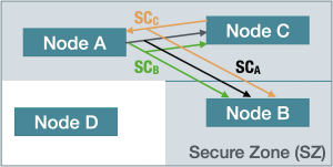
The CANsec concept defines Secure Zones (SZ) in which participating nodes can communicate securely with each other. The nodes have common information for transmitting frames to each other in an authenticated and, if necessary, encrypted form.
Nodes outside do not have this information and thus cannot inject frames or read encrypted frames from the SZ. This structuring also facilitates the key management of the network. Participants in an SZ can communicate with each other in so-called secure channels (SCs), as shown in Figure 1. Nodes A, B, and C can communicate securely with each other, while node D is left out and cannot read encrypted frames. Each of the SCs has a unique identifier (Secure Channel Identifier, or SCI for short) that is part of the CANsec header.
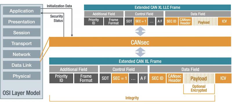
As shown in Figure 2, CANsec is located in the OSI model in the Data Link layer (Layer 2). From the application layer, initial data such as the key, Cipher Mode (CM), and an initial Freshness Value (FV) are required. The CANsec module uses the CAN XL LLC frame, the upper sublayer of the data link layer, as input.

Setting the Simple/Extended Content Bit (SEC) in the CAN XL header indicates that there is an extension in the data area of the CAN XL frame, which extends its data area accordingly. The inserted CANsec header starts with an identifier that shows which add-on it is. In this case, the identifier stands for the ID CANsec, but it could also contain another higher-layer protocol. Further CAN XL extensions, which are described in the standard as »Add-on Functions«, can also be executed in cascade.
In the case of a CANsec frame, the user‘s original payload is extended by the CANsec header at the beginning and the Integrity Check Value (ICV) at the end of the payload. The ICV is generated based on a message authentication algorithm that uses values from the CAN XL header and all values from the CANsec header and payload, which means values across the entire LLC frame.
The CANsec header consists of the Cipher Control Information (CCI) that contains the version number (VN) of the CANsec protocol and the Cipher Mode (CM). The CM indicates whether the frame is authenticated only or authenticated and encrypted. This is followed by the Secure Channel Identifier (SCI), which, together with the Association Number (AN), indicates the key set to be used. CANsec also uses a Freshness Value (FV) to avoid replay attacks. Another purpose of the FV is to provide the encryption algorithm with an initial value for further processing. The FV itself is not secret, but for cryptographic reasons, each initialization value may only be used once with a key. Therefore, the key is to be exchanged after 232 FV.
4. Proof of Concept – CANsec Performance Testing
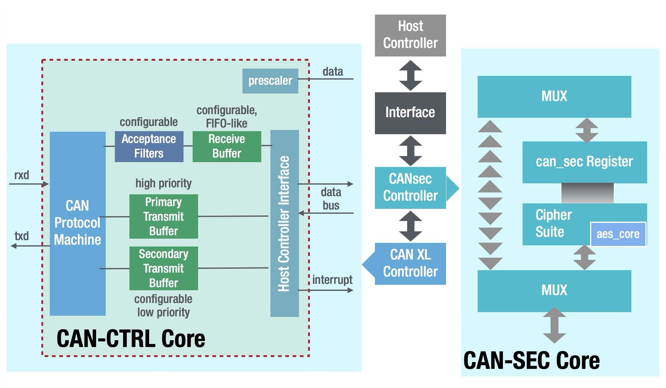
To investigate the performance regarding the transmission time of a CANsec implementation, Fraunhofer IPMS has carried out a Proof of Concept (PoC). For the PoC, Fraunhofer IPMS used the CAN bus cores available for licensing through CAST. The CAN-CTRL IP core offers a solution for CAN XL in addition to the CAN variants CAN 2.0 and CAN FD. The CAN-SEC IP core is used as the CANsec controller. Both IP cores are connected as a memory-mapped device to the bus of a host system, for example, to a microcontroller, as shown in Figure 3.
The host system stores frames in the buffer memory of the CAN-CTRL, which then transmits the data in a CAN-compliant manner and finally places them in the buffer memory, ready for collection by the host system. Several buffer memories can be provided for transmission and reception via parameters so that the host system can continuously provide and evaluate new data. In this way, a continuous data stream can be provided. The CAN-SEC IP core inserts the additional information into the buffer memory and authenticates and encrypts the data.

On the receiver side, the frame is also verified in a buffer memory and converted back to its original form. On the part of the CAN-CTRL IP core and CAN-SEC IP core, the same buffer memory can be used in each case so that no additional data transfer operations are necessary. The CAN-SEC also works with a simple buffer memory and can also process CANsec frames from other devices or handle the authentication and encryption of several CAN nodes in the host system. For authentication and optionally for encryption of the CANsec frame, the CAN-SEC IP core provides the Galois/Counter Mode (GCM). This uses the Advanced Encryption Standard (AES) as a basis, which can be used in the core with a key width of 128, 192, or 256 bits.
Both cores are available in a hardware description language that enables implementation and verification of the module in the target design. Through synthesis, this can then be easily implemented in FPGAs and ASICs.
In the PoC, the highest possible data rate of 20 Mbps and a key width of 256 bits were selected, which corresponds to the worst-case scenario. A clock frequency of 200 MHz was selected for the host system. Since header bytes are also transmitted in addition to user data bytes, the user data rate is lower than the transmission rate on the bus lines; in the selected example, the user data rate corresponds to 14.5 Mbps. There is a large dependency between the number of user data bytes and the data transmission time. This also applies on a different scale to the processing time of the CAN-SEC IP core.
Figure 4 shows the sequence and time duration of the individual steps of a CAN-XL transmission using the CAN-CTRL and the CAN-SEC. Approximately 0.5 µs elapse for the host system on the transmitter side to store the data to be transmitted in memory. The frame is then authenticated and encrypted by the CAN-SEC IP core, which takes another 2.7 µs. For transmitting and receiving the frame another 73 µs are needed. Verifying and decrypting on the receiver side costs another 2.3 µs, and 0.5 µs are required for fetching the frame.

Figure 4: CANsec transmission sequence
Figure 5 shows the duration of authentication and encryption as well as the transmission time of the CAN XL frame as a function of the user data length, and it compares them with each other. Since the duration of authentication and encryption is shorter than the actual CAN XL frame processing time, the maximum data rate of the CAN bus can be guaranteed in the example. If multiple buffer memories are used, the host and CAN-SEC transmission can already be prepared while the CAN-CTRL is still transmitting the previous frame, which means no additional waiting time (latencies).

Figure 6 shows an example with two successive frames of the same size, in which continuous transmission is ensured, and no additional latency is caused by authentication and encryption.

In special exceptional cases, additional latency may occur. Figure 7 shows two consecutive frames, the first of which is particularly short and the subsequent one very long. In this example, additional latency occurs because the duration of the authentication is longer than the transmission duration of the first CAN XL frame. The described behavior also applies in the reverse case for the receiver side, when a very short frame follows a very long one. However, this effect can only occur at transmission speeds of more than 10 Mbps, since only in these cases can the transmission of the shortest frame take longer than the encoding of the longer frame. For real application scenarios, this case is likely to occur rather rarely, since the vast majority of all nodes currently communicate at speeds of up to 10 Mbps.

5. Conclusion
Zonal E/E architectures provide the software-defined vehicle of the near future with the necessary flexibility and performance but pose new challenges in terms of cyber security. With AUTOSAR SecOC, a solution already exists that can protect signal-based communication from attacks, but this solution can be accompanied by high CPU utilization, which can lead to difficulties, especially in zonal architectures.
CANsec operates at the lower layers and is a comparatively resource-efficient solution for securing the CAN bus against the most common threats to which a CAN network can be exposed. In a proof of concept, it was shown that encryption and authentication of CAN XL frames is possible without latencies, and except for a few exceptional cases, transmission is possible without loss of bandwidth.
About Fraunhofer IPMS
The Fraunhofer-Gesellschaft, based in Germany, is the world‘s leading organization for application-oriented research. With its focus on future-relevant key technologies and on the exploitation of results in business and industry, it plays a central role in the innovation process. As one of 76 institutes, Fraunhofer IPMS works on electronic, mechanical, and optical components and their integration into miniaturized devices and systems. Our services range from conception and product development to pilot production in our own laboratories and clean rooms.
The business unit DCC develops IP cores such as CAN, LIN, Ethernet TSN and RISC V and works through CAST to license these to companies from various industries worldwide, with a special focus on automotive functional safety according to ISO-26262. In addition, Fraunhofer IPMS offers integration support, customer-specific adaptations and extensions, as well as analog and mixed-signal design for specific solutions.
About CAST
Computer Aided Software Technologies, Inc. (CAST) is a silicon IP provider founded in 1993. The company’s ASIC and FPGA IP product line includes microcontrollers and processors; compression engines for data, images, and video; interfaces for automotive, aerospace, and other applications; various common peripheral devices; and comprehensive SoC security modules.
Contact
[email protected]
CAST, 11 Stonewall Crt., Woodcliff Lake NJ USA 07677
+1 201.391.8300
www.cast-inc.com

